Wired up the voltmeter by taking hooking up the positive to the horn and grounding it to the bars underneath the horn switch.
Went right into the same mount as the speedo. Job done.
Showing posts with label DIY. Show all posts
Monday, July 15, 2019
Sunday, July 14, 2019
Red: Homemade 6V Voltmeter
Got a $10 voltmeter from Amazon (Chinese seller). Got an error as soon as I hooked it up to the battery but immediately realized it was meant for 12V and I'd just missed that in the title.
But then realized I at least had a nice metal body and I could perhaps swap out the guts of it with one of the 6V LEDs I already had.
Getting it open was the hardest part. Got the body off easy enough but the cap was really crimped on there tight keeping the plastic cover captive. Basically had to rip through and destroy the plastic inner shell to get anywhere near it.
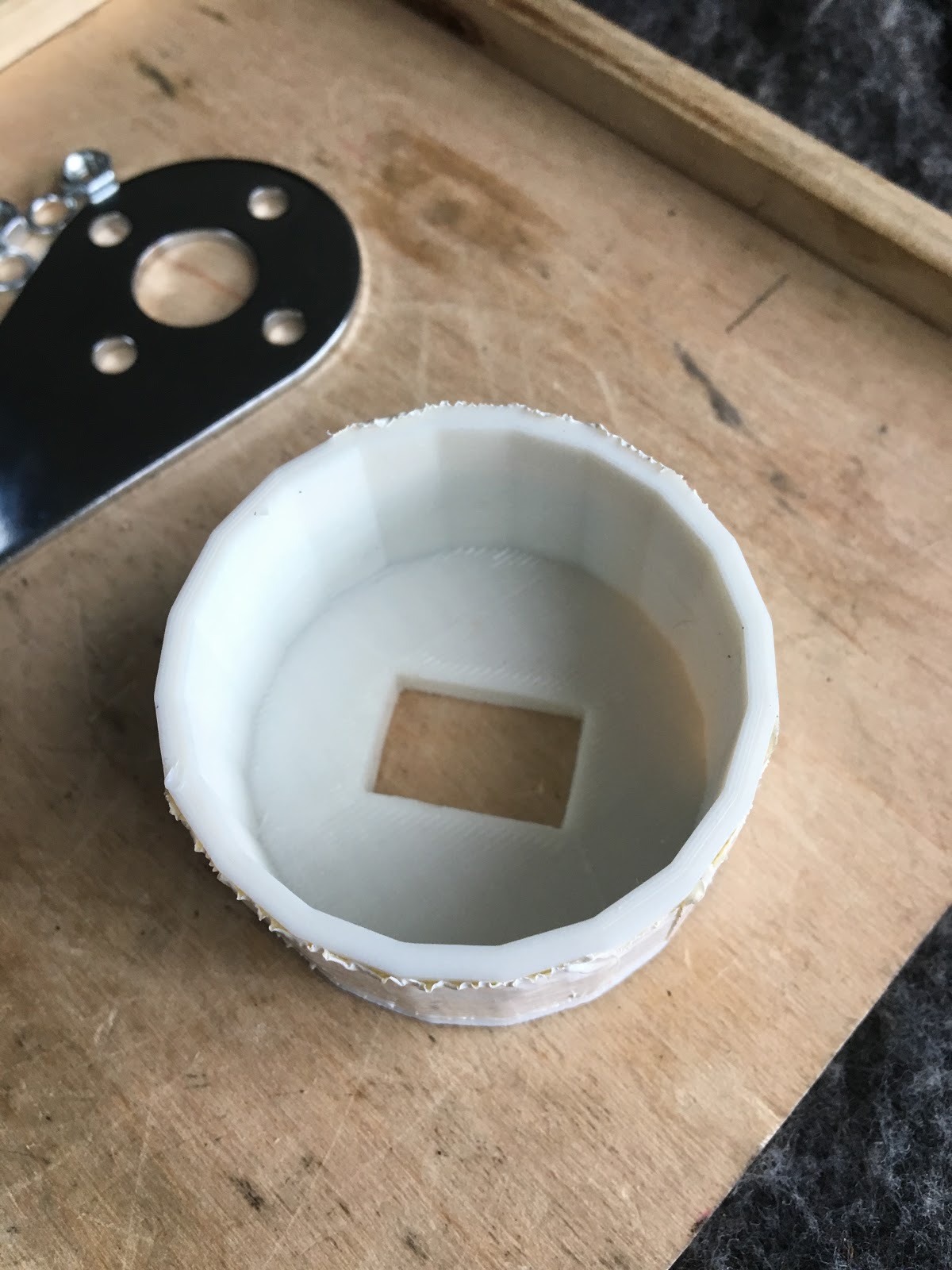
Relatively easy to 3d print a new inner body. Thought I'd have to also make some kind of fancy mount for the LED itself but found that it was easy enough to press fit it into the rectangular opening.
Final piece of luck was getting a couple big o-rings from the hardware store. Put a smaller one against the 3d body, then the clear plastic cover, then the thicker o-ring to keep it all in place. Worked a treat.
Bonus was that the blue LED looked much better than the original red 12V display.
But then realized I at least had a nice metal body and I could perhaps swap out the guts of it with one of the 6V LEDs I already had.
Getting it open was the hardest part. Got the body off easy enough but the cap was really crimped on there tight keeping the plastic cover captive. Basically had to rip through and destroy the plastic inner shell to get anywhere near it.
Relatively easy to 3d print a new inner body. Thought I'd have to also make some kind of fancy mount for the LED itself but found that it was easy enough to press fit it into the rectangular opening.
Final piece of luck was getting a couple big o-rings from the hardware store. Put a smaller one against the 3d body, then the clear plastic cover, then the thicker o-ring to keep it all in place. Worked a treat.
Bonus was that the blue LED looked much better than the original red 12V display.
Labels:
DIY,
electrical,
voltmeter
Saturday, June 2, 2018
Ivy Bike Stand, Round 2
Realized that it would be ideal to be able to slide the stool further over to the right, but that means it needs a groove for the oil bolt to slide into.
Used the Dremel attachment to set the right height and then just start cutting.
Theory worked out, but it's slow work. Ended up doing about 4-5 cm's worth. It's enough to get the stool solidly underneath the engine, but not enough to be able to bolt in the right side peg bolts.
Not sure if it's worth it to do that, though.
Maybe will just cut the holes for the two left-side bolts and then do a test to see if the other two are really needed.
Also did a test on the neutral wire. Oddly, found that when in neutral, testing from the wire to battery positive resulted in a very slight voltage, but definitely not enough to power the bulb. Not sure why there was some voltage but not a full 6v.
Used the Dremel attachment to set the right height and then just start cutting.
Theory worked out, but it's slow work. Ended up doing about 4-5 cm's worth. It's enough to get the stool solidly underneath the engine, but not enough to be able to bolt in the right side peg bolts.
Not sure if it's worth it to do that, though.
Maybe will just cut the holes for the two left-side bolts and then do a test to see if the other two are really needed.
Also did a test on the neutral wire. Oddly, found that when in neutral, testing from the wire to battery positive resulted in a very slight voltage, but definitely not enough to power the bulb. Not sure why there was some voltage but not a full 6v.
Labels:
bike stand,
DIY
Sunday, May 27, 2018
Ivy: Bike Stand, Round 1
After a few different (discarded) designs, decide to try to build a bike stand using the Clement Street wooden stool along with 90-degree steel braces from Ace.
For step one, just used a coping saw to cut down each leg until I could just barely squeeze the stool in under Ivy's engine.
Then added the four 90-degree brackets to give it a more stable stance.
For step one, just used a coping saw to cut down each leg until I could just barely squeeze the stool in under Ivy's engine.
Then added the four 90-degree brackets to give it a more stable stance.
Labels:
bike stand,
DIY
Monday, August 17, 2015
Spare Wheel: Truing Stand, Part 4
Putting even more time into truing practice, I've got the spare wheel down to a 0.4mm runout and a 1mm hop.
Did one more trip to Ace to get some magnets to make a tool holder and some magnetic pushpins to use for marking the rim at specific points. Used some spare metal strips to make metal runners for the magnetic base to attach to.
Also got a 5mm Motion Pro Ergo spoke wrench, which was a great piece of kit, but which then revealed that the aftermarket nipples I'm using aren't consistently 5mm! Some are slightly bigger meaning I have to switch back to the other wrench.
But all in all, absolutely loving the entire "workstation".
Features:
Did one more trip to Ace to get some magnets to make a tool holder and some magnetic pushpins to use for marking the rim at specific points. Used some spare metal strips to make metal runners for the magnetic base to attach to.
Also got a 5mm Motion Pro Ergo spoke wrench, which was a great piece of kit, but which then revealed that the aftermarket nipples I'm using aren't consistently 5mm! Some are slightly bigger meaning I have to switch back to the other wrench.
But all in all, absolutely loving the entire "workstation".
Features:
- Solid base to hold the swing arm including cork lined uprights with C-clamps (Nicko's idea!)
- Metal runners for attaching the dial gauge's magnetic base.
- Double tool holder magnets for the 2 spoke wrenches.
- Paper clip pointers showing both hop and runout simultaneously.
- Can be disassembled for long-term storage.
- Perhaps most importantly, it makes use of the previously wasted "wide" swing arm!
Sunday, August 16, 2015
Spare Wheel: Truing Stand, Part 3
After practicing truing for a couple days just using the pointer method, I decided I wanted to step up to a dial gauge. Found a nice metric one ($10) and also bought a magnetic stand ($20).
I went from a 2mm runout/hop down to 1mm using the gauge.
Friday, August 14, 2015
Spare Wheel: DIY Truing Stand, Part 2
One $50 trip to Ace and I got everything to make the stand. Spent quite awhile at the store, though, thinking through different approaches to make the base. Lucked out in finding some hinges that would hold the 3/8 x 10" thru-bolt perfectly and could then be bolted down to the base.
Ace selling the plywood board was key, too. Also finally put the new $20 cordless drill to good use.
Honestly can't believe it worked out so well...
Ace selling the plywood board was key, too. Also finally put the new $20 cordless drill to good use.
Honestly can't believe it worked out so well...
Thursday, August 13, 2015
Spare Wheel: DIY Truing Stand, Part 1
First step to building the truing stand is to see if I can get the wheel nice and tight on the axle using the spacers I have. By adding in a few 12mm washers, I got the rear wheel locked in perfectly.
Ended up using the stock "H" spacer on the right. On the left used the axle sleeve + 3 washers + stock block washer.
Did a little truing just by holding the swingarm up with one hand. Next step, build a platform to hold the swingarm up!
Ended up using the stock "H" spacer on the right. On the left used the axle sleeve + 3 washers + stock block washer.
Did a little truing just by holding the swingarm up with one hand. Next step, build a platform to hold the swingarm up!
Monday, April 28, 2014
Roxy: DIY 5mm Screws Tested
Somewhat shocked to find the screw worked. And I was able to thread it with my fingers the entire length. It did cinch down tight at the end, though. I'm wondering if that's too loose...?
Then I cut 3 more screws to see how the die would hold up. By the 3rd one (4th overall) it was getting a bit hard to get the screw to bite in at first. Also seemed like the screw was turning crookedly.
Yet the finished screw looked good, with clean threads at the right pitch.
It would be perfect if these socket screws weren't hardened alloy, but they don't seem to sell them any other way. And I can't find regular pan heads in #12-28 either.
Still, if you could cut a half dozen screws before the die gave out, you'd still come out a little ahead of eBay.
Then I cut 3 more screws to see how the die would hold up. By the 3rd one (4th overall) it was getting a bit hard to get the screw to bite in at first. Also seemed like the screw was turning crookedly.
Yet the finished screw looked good, with clean threads at the right pitch.
It would be perfect if these socket screws weren't hardened alloy, but they don't seem to sell them any other way. And I can't find regular pan heads in #12-28 either.
Still, if you could cut a half dozen screws before the die gave out, you'd still come out a little ahead of eBay.
Sunday, April 27, 2014
Roxy: DIY 5mm JIS Screws Continued
Ok, the second attempt to cut these 5mm JIS screws. This time using #12-28 socket cap screws. Amazingly, the #12-28 pitch is almost exactly 0.9 to begin with. The problem is just that the screw is much bigger than 5mm, so you have to remove a lot of material.
Turning it through the die was definitely work, and you can feel the metal cutting. Was worried how well the die itself would hold up cutting the alloy.
The screw before cutting. It's already 0.9 to start.
About halfway through and you can see how much material has to be removed.
Compared to the original.
Now I just have to TEST IT...
Turning it through the die was definitely work, and you can feel the metal cutting. Was worried how well the die itself would hold up cutting the alloy.
The screw before cutting. It's already 0.9 to start.
About halfway through and you can see how much material has to be removed.
The finished screw.
Compared to the original.
Checking the pitch on the gauge.
Now I just have to TEST IT...
Labels:
1964 S90,
DIY,
fabrication,
JIS
Wednesday, April 9, 2014
Aw Nuts
Lesson learned: not all steel is created equal - check the grade!! I had high hopes that I'd be able to cut the 5mm JIS screws, but ended up killing the die instead.
I found a couple of socket cap screws (#4 hex) at ACE that had a good length of un-threaded metal.
For my first attempt, I cut the screw thinking that I could just get the unthreaded part to bite into the die. But it wouldn't catch (and I only realized why later).
So then I tried cutting most of the length, but leaving enough thread so I could get it started in the die.
Then start cutting. This was all going very well until the screw seemed to turn without moving. I figured it had just hit the unthreaded metal and needed more downward pressure. I was wrong.
Had to knock the screw back out with the ball peen. Upon inspection, it looks like the threads pulled the metal down but instead of being cut, it simply flattened the grooves in the die.
Could it be because it was 12.9 grade steel?
I found a couple of socket cap screws (#4 hex) at ACE that had a good length of un-threaded metal.
For my first attempt, I cut the screw thinking that I could just get the unthreaded part to bite into the die. But it wouldn't catch (and I only realized why later).
So then I tried cutting most of the length, but leaving enough thread so I could get it started in the die.
Then start cutting. This was all going very well until the screw seemed to turn without moving. I figured it had just hit the unthreaded metal and needed more downward pressure. I was wrong.
Had to knock the screw back out with the ball peen. Upon inspection, it looks like the threads pulled the metal down but instead of being cut, it simply flattened the grooves in the die.
Could it be because it was 12.9 grade steel?
Monday, April 7, 2014
Roxy: DIY JIS Screws, First Attempt
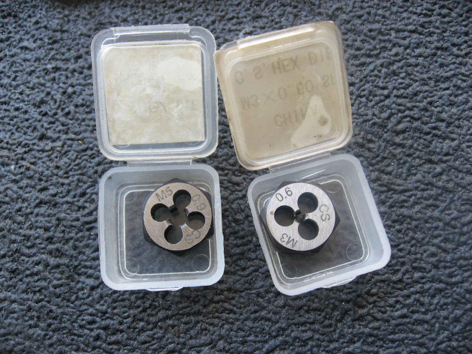
Received 2 new dies today: 5mm 0.9 pitch and 3mm 0.6 pitch. Once again hoping to free myself from outrageous eBay prices.
First test was to try to cut a 5x10 screw for the points plate. I held the die in place with the socket wrench, while turning it with the JIS vessel screwdriver. Luckily, I was able to turn it by hand through the entire length.
I used a little WD40 as lube, and I would back off and resume any time it started to get hard to turn. Toward the end, I had to switch to holding it with a box wrench, as I think it bottomed out in the socket. But even then, it just took a little elbow grease.
When I was done, the screw turned very easily in the die. But checking it against the thread gauge, it was definitely not a clean 0.9 pitch. It wasn't 0.8, either, so the die definitely recut it a bit - just not enough.
I could hand thread it three full turns in the actual hole (points plate), but I didn't dare force it any further than that.
Asked for advice on Yahoo Groups and a good suggestion came back: find a long screw that has solid metal between the head and the threads. Cut the threads off, then use that to cut fresh new threads in the die.
So there's still some hope...
Also, the screws that hold the points to the plate are 4mm x 6-ish at 0.7 pitch (ie, NOT JIS). And note they have both a split ring and a regular washer.
First test was to try to cut a 5x10 screw for the points plate. I held the die in place with the socket wrench, while turning it with the JIS vessel screwdriver. Luckily, I was able to turn it by hand through the entire length.
I used a little WD40 as lube, and I would back off and resume any time it started to get hard to turn. Toward the end, I had to switch to holding it with a box wrench, as I think it bottomed out in the socket. But even then, it just took a little elbow grease.
When I was done, the screw turned very easily in the die. But checking it against the thread gauge, it was definitely not a clean 0.9 pitch. It wasn't 0.8, either, so the die definitely recut it a bit - just not enough.
I could hand thread it three full turns in the actual hole (points plate), but I didn't dare force it any further than that.
Asked for advice on Yahoo Groups and a good suggestion came back: find a long screw that has solid metal between the head and the threads. Cut the threads off, then use that to cut fresh new threads in the die.
So there's still some hope...
Also, the screws that hold the points to the plate are 4mm x 6-ish at 0.7 pitch (ie, NOT JIS). And note they have both a split ring and a regular washer.
Thursday, April 3, 2014
DIY Gaskets
Starting down the path of freeing myself from outrageous eBay prices on trivial items!
First stop, cutting gaskets for the carbs. It was pretty fiddly at first, until I realized I was going about it all wrong. I had started by trying to cut a replica of the original gasket, then trimming it to fit better. Took me awhile to realize I should just be using the body itself to make the pattern. Duh.
Step 1: get all your arts and crafts gear.
Cut one out of paper to get the technique down and work out any kinks.
Grab a roll of gasket material. In this case, it needs to be the kind treated to withstand gas.
Trace the pattern on your gasket material. The hole in the gasket and through the cardboard is to allow the overflow tube to poke through a bit so that the carb can sit flush on a flat surface.
Mark off 1/8" all around.
Use the carb again to trace the inner contoured line.
Then it's X-acto time.
Moment of truth!
Compared side to side (DIY version on the left), you can see that they were slightly different. The original gasket never quite fit the body correctly, though maybe it was the wrong part in the first place.
First stop, cutting gaskets for the carbs. It was pretty fiddly at first, until I realized I was going about it all wrong. I had started by trying to cut a replica of the original gasket, then trimming it to fit better. Took me awhile to realize I should just be using the body itself to make the pattern. Duh.
Step 1: get all your arts and crafts gear.
Cut one out of paper to get the technique down and work out any kinks.
Grab a roll of gasket material. In this case, it needs to be the kind treated to withstand gas.
Trace the pattern on your gasket material. The hole in the gasket and through the cardboard is to allow the overflow tube to poke through a bit so that the carb can sit flush on a flat surface.
Mark off 1/8" all around.
Use the carb again to trace the inner contoured line.
Then it's X-acto time.
Moment of truth!
Compared side to side (DIY version on the left), you can see that they were slightly different. The original gasket never quite fit the body correctly, though maybe it was the wrong part in the first place.
Labels:
DIY,
gasket inventory,
gaskets
Subscribe to:
Posts (Atom)